Velleman-projects K8045 Assembly instructions Manuel d'utilisateur
Naviguer en ligne ou télécharger Manuel d'utilisateur pour Matériel Velleman-projects K8045 Assembly instructions. Velleman projects K8045 Assembly instructions User Manual Manuel d'utilisatio
- Page / 20
- Table des matières
- MARQUE LIVRES
Résumé du contenu
Modifications reserved Features : Add an LCD display to any low-tech application and make it look high-tech ! Replace up to 9 indicators or lamps
10 1. Hook-up when using an adapter : 2. Hook-up when using a transformer Connection 23. Connection LNTRANSFORMERK8045SW3GND87
11 How to construct an RS232 cable : Or you can buy a pre-assembled cable. Careful : this is not a null-modem cable How to establish a w
12 Turn RV1 (contrast) fully anti-clockwise. Set dipswitches SW1 (mode) to the ‘off’-position. Set jumper SK3 for ‘cable’-operation but do not c
13 The K8045 can store 9 sixteen-character messages, 1 for each input and a 9th which is displayed when no inputs are active. Briefly press SW2 ‘PROG
14 The K8045 features 4 operating modes, selectable with dipswitch SW1. To ensure correct operation, disconnect power before changing dipswitch posit
15 Options : RF wireless link : ... RX433/TX433 HQ supertwist LCD display :
16 3. Application with K8023 “Two wire 10-channel remote control” 12 ... 15Vin+ VTX123410+ Vext98765GNDGNDVAVB12345678GNDGND-COM+ VTX 1234567891012V
17 PCB & DIAGRAMS
18 PCB PCB
19 Diagrams Diagram
2 Assembly hints 1. Assembly (Skipping this can lead to troubles ! ) Ok, so we have your attention. These hints will help you to make this project s
VELLEMAN COMPONENTS NV Legen Heirweg 33 9890 Gavere Belgium Europe Info & support: www.velleman.be Modifications and typographical errors reserve
3 Assembly hints 1.3 Soldering Hints : 1- Mount the component against the PCB surface and carefully solder the leads 2- Make sure the solder jo
4 COLOR= 2… 5COLOR= 2...5 Color code table I P E SF S DK N D GB F NL C O D E CODICE COLORE CODIGO DE CORES CODIGO DE COL-ORES VÄRI KOODI
5 Construction J1 J2 J3 1. Jumperwire D1 : 1N4007 D2 : 1N4007 D3 : 1N4148 D4 : 1N4148 D5 : 1N4148 D6 : 1N4148
6 Construction SW2 SW3 7. Push buttons R6 : 1K (1 - 0 - 2 - B) R9 : 1K (1 - 0 - 2 - B) R12 : 1K (1 - 0 - 2 - B)
7 Construction SK3 : 3p 14. Header SK2 15. DC-jack SK5 : SUB-D 9p female 16. SUB-D connector
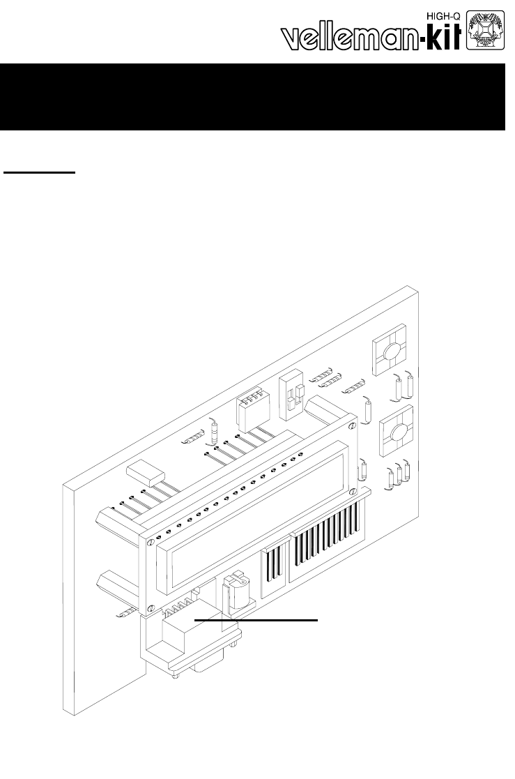
8 LCD assembling Cut the 20 pole connector to a 16 pole connector. Mount the 16 pole female connector. (see fig. 2.0)
9 Assembly Fit the display at the component side of the base PCB using four M2,5 bolts to-gether with four 15mm spacers. Fix the display using four M2
Produits connexes et manuels pour Matériel Velleman-projects K8045 Assembly instructions
 (12 pages)
© 2020, manymanuals.fr. Tous droits réservés | 0.893 s |
 Manymanuals.com
 Manymanuals.de
 Manymanuals.fr
 Manymanuals.it
 Manymanuals.pl
 Manymanuals.cz
 Manymanuals.es
 Manymanuals-pt.com
Commentaires sur ces manuels