Velleman-projects K7101 Assembly instructions Manuel d'utilisateur
Naviguer en ligne ou télécharger Manuel d'utilisateur pour Matériel Velleman-projects K7101 Assembly instructions. Velleman projects K7101 Assembly instructions User Manual Manuel d'utilisatio
- Page / 12
- Table des matières
- MARQUE LIVRES
Résumé du contenu
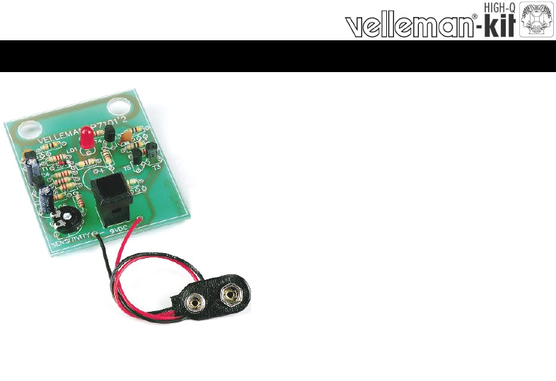
MAINS VOLTAGE DETECTOR K7101 ILLUSTRATED ASSEMBLY MANUAL H7101IP-1 Total solder points: 68 Difficulty level: beginner 1 2 3 4 5 advanced W
10 11. PCB PCB
Modifications and typographical errors reserved © Velleman Components nv. H7101IP - 2007 - ED1 VELLEMAN Components NV Legen Heirweg 33 9890 Gavere Bel
3 With this kit one can easily determine whether a wire is live or not. This kit can be used to detect wiring within walls or breaks in cabling. A fl
4 Assembly hints 1. Assembly (Skipping this can lead to troubles ! ) Ok, so we have your attention. These hints will help you to make this project s
5 Assembly hints 1.3 Soldering Hints : 1- Mount the component against the PCB surface and carefully solder the leads 2- Make sure the solder join
6 R1 : 4M7 (4 - 7 - 5 - B) R2 : 4M7 (4 - 7 - 5 - B) R3 : 8K2 (8 - 2 - 2 - B) R4 : 47K (4 - 7 - 3 - B) R5 : 470 (4 - 7
7 Construction RV1 : 470 7. Trim potentiometer RV1 SW1 : 1p 8. Push button LD1 : 5mm red 6. LED. Watch the
8 Connect a 9V battery to the holder. Stand at a location which is certain to have no mains cabling in the vicinity. Turn the RV1 potentiometer
9 Diagram 10. DIAGRAM
Produits connexes et manuels pour Matériel Velleman-projects K7101 Assembly instructions
 (16 pages)
© 2020, manymanuals.fr. Tous droits réservés | 0.806 s |
 Manymanuals.com
 Manymanuals.de
 Manymanuals.fr
 Manymanuals.it
 Manymanuals.pl
 Manymanuals.cz
 Manymanuals.es
 Manymanuals-pt.com
Commentaires sur ces manuels