Velleman-projects K7102 Assembly instructions Manuel d'utilisateur
Naviguer en ligne ou télécharger Manuel d'utilisateur pour Matériel Velleman-projects K7102 Assembly instructions. Velleman projects K7102 Assembly instructions User Manual Manuel d'utilisatio
- Page / 12
- Table des matières
- MARQUE LIVRES
Résumé du contenu
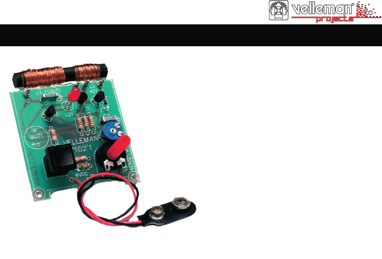
METAL DETECTOR K7102 ILLUSTRATED ASSEMBLY MANUAL H7102IP Total solder points: 47 Difficulty level: beginner 1 2 3 4 5 advanced Avoid disas
10 13. Diagram Diagram 1n2*3n3
VELLEMAN NV Legen Heirweg 33 9890 Gavere Belgium Europe www.velleman.be www.velleman-kit.com
Modifications and typographical errors reserved © Velleman nv. H7102IP’1 (rev.4) - 2014 5 410329 289683VELLEMAN NV Legen Heirweg 33, B-9890 GAVERE
2 To come up against an electric cable while drilling a hole in a wall can have catastrophic consequences. Likewise, drilling into gas, water pipes or
3 Assembly hints 1. Assembly (Skipping this can lead to troubles ! ) Ok, so we have your attention. These hints will help you to make this project su
DO NOT BLINDLY FOLLOW THE ORDER OF THE COMPONENTS ONTO THE TAPE. ALWAYS CHECK THEIR VALUE ON THE PARTS LIST! REMOVE THEM FROM THE TAPE ONE AT A TIME !
5 Construction D1 : 1N4148 2. Diode. Watch the polarity ! D. ..CATHODE ZD1 : 3V9 3. Zenerdiode. Watch the polarity ! CATHODEZD... The co
6 Construction & connection Choose C1 : C1 : 1n2 (122) C1 : 3n3 (332) C2 : 47nF (473) 5. Capacitors. C... LD1 : 5mm RED
7 Assembly Connect the battery terminal to the point marked “+” (red) and “-” (black), see figure 2.0. Connect the windings to their
8 Test 1. Connect a 9V battery to the battery holder. 2. Go to a place where NO metal object is known to be in the vicinity. 3. Turn preset RV1 fu
9 12. PCB layout. PCB
Produits connexes et manuels pour Matériel Velleman-projects K7102 Assembly instructions
 (1 pages)

 (28 pages)
© 2020, manymanuals.fr. Tous droits réservés | 1.230 s |
 Manymanuals.com
 Manymanuals.de
 Manymanuals.fr
 Manymanuals.it
 Manymanuals.pl
 Manymanuals.cz
 Manymanuals.es
 Manymanuals-pt.com
Commentaires sur ces manuels