Velleman-projects K8048 Assembly instructions Manuel d'utilisateur
Naviguer en ligne ou télécharger Manuel d'utilisateur pour Matériel Velleman-projects K8048 Assembly instructions. Velleman projects K8048 Assembly instructions User Manual Manuel d'utilisatio
- Page / 12
- Table des matières
- MARQUE LIVRES
Résumé du contenu
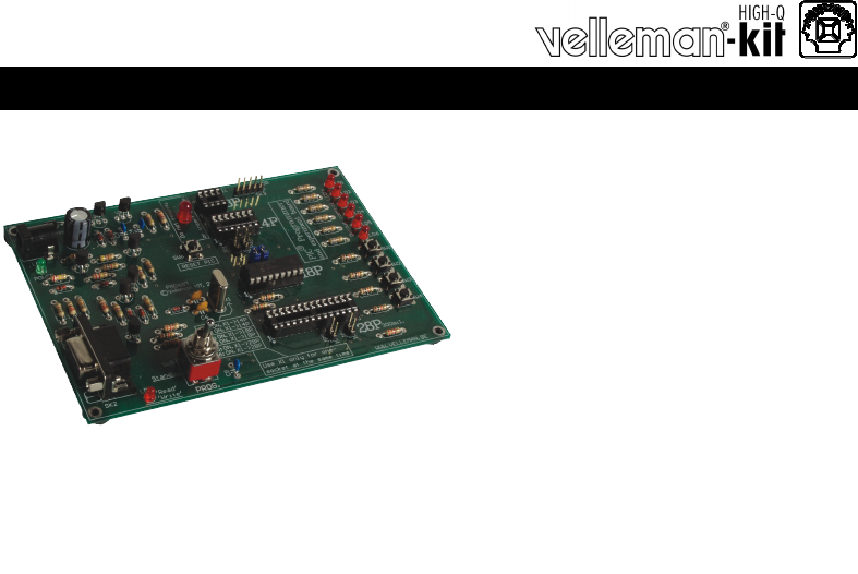
K8048 ILLUSTRATED ASSEMBLY MANUAL H8048IP-1 Total solder points: 274 Difficulty level: beginner 1 2 3 4 5 advanced PIC® PROGRAMMER AND
10 20. Schematic diagram. Schematic diagram
11 PCB 21. PCB
5 410329 291952Modifications and typographical errors reserved - © Velleman nv. H8048IP - 2004 - ED1 (rev. 5.0)
FR Vous trouverez la traduction de cette notice sur le CD, avec d'autres informations NL Vertaling van deze handleiding, als ook meer gegevens
3 Features: Suitable for programming Microchip® FLASH PIC(tm) microcontrollers Supports 4 different 300 mil. PICs: 8p, 14p, 18p and 28p Test bu
4 Assembly hints 1. Assembly (Skipping this can lead to troubles ! ) Ok, so we have your attention. These hints will help you to make this project s
5 Assembly hints 1.3 Soldering Hints : 1- Mount the component against the PCB surface and carefully solder the leads 2- Make sure the solder j
6 R1 : 15K (1 - 5 - 3 - B) R2 : 220K (2 - 2 - 4 - B) R3 : 4K7 (4 - 7 - 2 - B) R4 : 1K (1 - 0 - 2 - B) R5 : 15K
7 T1 : BC547 T2 : BC547 T3 : BC557 T4 : BC547 T5 : BC547 Construction 8. Transistors. IC1 : 8P IC2 : 14P IC3 : 18P IC4
8 SK3 : 5P C1 : 220µF 15. Electrolytic Capacitor. Watch the polarity ! C...Construction LD9 : Blinking red (5mm) LD1CATHO
9 Mount the rubber feet on the solder side of the PCB, see fig 1.0. 17. Rubber feet Construction • Place the Velleman® software CD in your
Produits connexes et manuels pour Matériel Velleman-projects K8048 Assembly instructions
 (1 pages)

 (32 pages)
© 2020, manymanuals.fr. Tous droits réservés | 0.905 s |
 Manymanuals.com
 Manymanuals.de
 Manymanuals.fr
 Manymanuals.it
 Manymanuals.pl
 Manymanuals.cz
 Manymanuals.es
 Manymanuals-pt.com
Commentaires sur ces manuels